SWMM 5.0 Update History
=======================
------------------------
Build 5.0.020 (08/23/10)------------------------
Engine Updates

1.  A refactoring bug that prevented SWMM from reading rainfall data
    from external rainfall files was fixed. See gage.c.
------------------------
Build 5.0.019 (08/30/10)
------------------------
Engine Updates
1.  The ability to explicitly model five different types of Low Impact
    Development (LID) practices at the subcatchment level has been
    added. Consult the LID Controls topic in the Help file for details.
    See lid.c, lid.h, infil.c, infil.h, input.c, inputrpt.c, project.c,
    statsrpt.c, and subcatch.c.

2.  Pollutant buildup over a given landuse can now be specified by a time
    series instead of just a buildup function. Consult the Land Uses /
    Buildup topic in the Help index for more details. See landuse.c and
    keywords.c.
3.  An option was added to allow evaporation of standing water to occur
    only during periods with no precipitation (the default is the current
    practice of allowing evaporation in both wet and dry periods). See
    climate.c, enums.h, keywords.c, objects.h, project.c, subcatch.c,
    and text.h.
4.  Storage node losses from evaporation and infiltration are now computed
    directly within the flow routing routines to produce better
    conservation of mass. See objects.h, routing.c, dynwave.c and node.c.
5.  The check to see if flow in a link should not exceed the normal flow
    now uses just the upstream Froude number rather than both up and
    downstream numbers. See dynwave.c.

6.  The maximum trials used when evaluating the flow and head equations at
    a given time period for dynamic wave routing was increased from 4 to 8.
    See dynwave.c.
7.  The Ponding calculation for dynamic wave flow routing was changed once
    again to obtain better continuity results. The depth in a surcharged
    node that can pond is not allowed to rise higher than just beyond full
    depth in any single time step. After that, its change in depth is
    determined by the node's ponded area. Similarly, the depth of a ponded
    node is not allowed to drop more than just below full depth in any
    single time step. See dynwave.c and node.c.
8.  For Kinematic Wave and Steady Flow routing, a node's ponded area is
    no longer used to infer a ponded depth when a node floods with Ponding
    turned on. Instead, the water depth is simply set to the node's maximum
    depth and the ponded area parameter is simply used as a indicator as
    to whether the node can pond or not. (This differs from dynamic wave
    routing where the ponded area directly influences ponded depth through
    the solution of the momentum and flow conservation equations.) See
    flowrout.c.

9.  As a consequence of the preceeding update, the Node Flooding Summary
    table in the Status Report no longer displays the maximum ponded volume
    in acre-inches (or hectare-mm). Instead it displays the maximum ponded
    depth (ft or m) for Dynamic Wave flow routing or the maximum ponded
    volume (1000 ft3 or 1000 m3) for other forms of routing. See stats.c
    and statsrpt.c.
10. The groundwater mass balance equations were returned to the form they
    had in release 5.0.013 since they were not correctly accounting for
    the water volume transferred between the saturated and unsaturated
    zones due only to a change in the water table depth. See gwater.c.

11. Controls based on flow rates now properly account for the direction of
    flow when they are evaluated. This may require users to add an extra
    condition clause to a rule that only applies for flow in the positive
    direction (e.g., AND Link XXX FLOW >= 0.0). See controls.c.
12. The Villemonte correction for downstream submergence is now also used
    for partly filled orifices (instead of just for weirs). See link.c and
    dynwave.c.
13. A missing term in the equation used to check for submerged inlet
    control for Culvert conduits was fixed. See culvert.c.
14. If a non-conduit link is connected to a storage node then its
    contribution to the node's surface area is now ignored. See
    dynwave.c.
15. The automatic adjustment of the maximum depth of a link's end nodes
    to be at least as high as the link's crown no longer applies when
    the link is a bottom orifice. See link.c.

16. A fatal error message is now generated if a conduit's entrance,
    exit, or average loss coefficient value is negative. See link.c.

17. Requests to do internal routing of runoff between impervious and
    pervious sub-areas of a subcatchment when only one type of sub-area
    exists are now ignored. See subcatch.c.

18. The check on the error condition of a node having both incoming and
    outgoing dummy conduits was modified so as not to get fooled by
    Outlet-type links. See toposort.c.

19. The Ignore Snowmelt switch is now internally set to true whenever
    there are no snow pack objects defined, so that precipitation is not
    mistakenly converted to snow for a project with temperature data.
    See gage.c and project.c.

20. When reading min/max daily temperatures from a climate file, the
    values are now swapped if the minimum is greater than the maximum.
    See climate.c.

21. When the Hargreaves method is used to compute an evaporation rate
    from daily temperature values, negative rates are no longer allowed.
    See climate.c.

22. Several bugs that prevented SWMM from detecting and reading Canadian
    DLY02/04 climate files correctly were fixed. See climate.c.

23. An error message is now generated if a time series used for rainfall
    is also used for another purpose in a project (since it will cause
    the two uses to be out of synch). See error.h, error.c, gage.c,
    climate.c, control.c, and inflow.c.

24. An error message is now generated if two Rain Gages with files as
    their data source use the same Station IDs but different names for
    the data file. See rain.c, error.h, and error.c.

25. When zero rainfall values appear in a rain file or time series they
    are now skipped over and treated as a dry period, the same as would
    occur had they not been entered in the first place. See gage.c.

26. A bug that caused the data in an evaporation time series to be out
    of synch with the simulation time clock has been fixed. This only
    affected evaporation data supplied from time series and not monthly
    average data or data from climate files. See climate.c.

27. The water quality mass balance now correctly accounts for any initial
    mass in the system created by using a hot start file. See massbal.c.

28. For models that only compute runoff and have a reporting time step
    less than the wet time step, the latter is internally set equal to
    the former. See swmm5.c.

GUI Updates

1.  The Data Browser was updated to include the newly added Low Impact
    Development (LID) objects and new dialog forms were added to specify
    LID design data and their placement within a project's subcatchments.

2.  You can now open a project input file by dragging it from Windows
    Explorer (or the Desktop) and dropping it anywhere in SWMM's main
    window.

3.  A new checkbox was added to the Evaporation page of the Climatology
    Editor to include the option to evaporate only in dry periods.

4.  The choices for Function type on the Buildup page of the Land Use
    Editor were extended to include an external time series (EXT).

5.  SWMM will now continue to use the period (".")  as the decimal
    separator even if the user or the system changes the Windows Regional
    Settings while the program is running.

6.  A new installer program is now used that places the example data sets
    in the user's My Documents\EPA SWMM Projects folder.

7.  The components below the horizonal splitter bar on the Data Browser
    panel were placed in their own panel component so that the splitter
    would work correctly under Windows 7.

------------------------
Build 5.0.018 (11/18/09)
------------------------
Engine Updates

1.  Reporting of the total infiltration + evaporation loss for each
    Storage Unit (as a percent of total inflow to the unit) was added
    to the Storage Volume Summary table in the Status Report. See
    objects.h, node.c, stats.c, and statsrpt.c.

2.  Double counting the final stored volume when finding the nodes with
    the highest mass balance errors has been eliminated. See stats.c.

3.  A warning message was added for when a Rain Gage's recording
    interval is less than the smallest time interval appearing in its
    associated rainfall time series. (An error message is issued if
    the recording interval is greater than the smallest time series
    interval.) See gage.c and text.h.

4.  Hot Start interface files now contain the final state of each
    subcatchment's groundwater zone in addition to the node and
    link information they have always had. See routing.c.

5.  To avoid confusion, the actual conduit slope is now listed in the
    Link Summary table of the Status Report rather than the adjusted
    slope that results from any conduit lengthening. See link.c and
    dynwave.c.

6.  The Status Report now displays only those summary tables for
    which results have been obtained (e.g., if the Flow Routing
    option is turned off, then no node or link tables are displayed).
    See massbal.c and statsrpt.c.

7.  Some code re-factoring was done to place rain gage validation
    and initialization in separate functions. See project.c, gage.c,
    and funcs.h.

8.  The engine version number was updated to 50018 (this update had
    been overlooked since release 5.0.010). See consts.h.

GUI Updates

1.  A bug that prevented Status Report files from being deleted from
    a users TEMP folder when they were no longer in use was corrected.
    Users should check their TEMP folders (usually in
    c:\Documents and Settings\<User Name>\Local Settings\Temp)
    for old files that begin with "swm". These can safely be deleted.

2.  The project input file created for use by SWMM's Add-On Tools now
    contains all project data, including map coordinates and element
    tags.


-----------------------
Build 5.0.017 (10/7/09)
-----------------------
Engine Updates

1.  The Ponding routine for dynamic wave flow routing was once
    again modified, this time to account for the special case
    where a node transitions between surcharged and ponded
    conditions within a single time step. This should correct
    the large continuity errors experienced with ponding under
    release 5.0.016. See dynwave.c.

2.  Error 112 (a conduit's elevation drop exceeds its length)
    is now treated as a Warning condition and not a fatal error.
    In this case the conduit's slope is computed as in earlier
    versions of SWMM (elevation drop / length) instead of using
    the more rigorous right-triangle method of HEC-RAS. See
    link.c and text.h.

3.  Inflow interface files no longer have to contain data for
    all of the same pollutants defined in the current project
    (e.g., they can contain just flows or some subset of the
    pollutants). See iface.c.

4.  Instead of using the rain gage's recording interval as the
    time step for processing a set of RDII unit hydrographs, the
    smaller of the wet runoff time step and the time to peak of
    the shortest unit hydrograph in the set is now used. As a
    result, it is now permissible to use hydrographs whose time
    to peak is shorter than the rain gage recording interval.
    See rdii.c.

5.  Under Curve Number infiltration, infiltration now stops when
    the maximum capacity (initially equal to 1000/CN - 10 inches)
    is completely used up. See infil.c.

6.  The small tolerance used to determine how much ponded depth
    in excess of depression storage is needed to initiate runoff
    was removed. This produces a smoother runoff response for
    some data sets. See subcatch.c.

7.  A default concentration for dry weather flow has been added
    to the Pollutant object. It can be overriden for any specific
    node by editing the node's Inflows property. See landuse.c,
    routing.c, and objects.h.

8.  For water quality routing, the simplified analytical
    solution to the CSTR mixing equation was replaced with a
    more robust finite difference approximation. This seems
    to avoid numerical problems with high decay rates. See
    qualrout.c.

9.  First order decay was not being applied to pollutants
    transported through conduits under Steady Flow routing. To
    do this correctly required writing a special water quality
    routine just for Steady Flow routing. See qualrout.c.

10. A small minimum depth tolerance was introduced for treatment
    to occur at nodes and to have non-zero concentrations in
    conduits. See qualrout.c.

11. Large water quality mass balance errors in systems that
    provide treatment at nodes were eliminated by correctly
    accounting for both the inflow mass and mass in storage
    when computing the mass lost to treatment. See treatmnt.c.

GUI Updates

1.  The property editor for Pollutant objects was modified to
    accommodate the new default dry weather flow concentration
    property.

2.  The default dry weather runoff time step was reduced from
    15 to 5 minutes and the default total duration was changed
    from 0 to 6 hours.

3.  The Ruler tool now displays a small square where the user
    begins their measurement so that its easier to create a
    closed polygon when measuring an area.


-----------------------
Build 5.0.016 (6/22/09)
-----------------------
Engine Updates

1.  A new option was added to compute daily evaporation from the
    daily temperature values contained in a climate file using
    Hargreaves' method. (See climate.c, enums.h, keywords.h, and
    text.h).

2.  When the Ponding option is turned on, nodes that can pond are no
    longer always treated like storage nodes that never surcharge.
    Now they are only treated this way after ponding occurs. Otherwise
    they behave like a normal node. (See dynwave.c).

3.  The small tolerance used to decide when a storage node was full or
    not has been removed since for very small time steps it could cause
    a currently full storage unit to remain full even if there was some
    small net outflow from it. (See node.c).

4.  Spurious warnings for negative elevation offsets no longer appear
    when the "*" entry is used for the offset value or when the offset
    elevation value is within a small tolerance of the node invert
    elevation. (See link.c).

5.  When the water level at a storage node exceeds the highest level
    supplied in its Storage Curve, an extrapolated surface area from
    the curve is now used only if the curve is sloping outward (i.e.,
    surface area is increasing with depth at the top of the curve). If
    instead it slopes inward then the last surface area entry in the
    curve is used. (See table .c).

6.  Comma delimited NCDC rainfall files, both with and without station
    name, can now be recognized and read correctly by SWMM. (See rain.c).

7.  Space delimited NCDC rainfall files with empty spaces in the condition
    code fields can now be read correctly. (See rain.c).

8.  A bug created in release 5.0.015 that caused incorrect RDII inflows
    to be computed when the rain gage recording interval was less than
    the runoff wet time step has been fixed. (See rdii.c).

9.  A new error check was added to detect if the time base of an RDII
    unit hydrograph is less than its rain gage recording interval.
    (See rdii.c).

GUI Updates

1.  The Evaporation page of the Climate Editor was modified to accommodate
    the new option for computing evaporation from daily temperatures.

2.  Evaporation Rate has been added to the list of System variables that
    can be viewed in time series plots and tables.

3.  The term "Shape Curve" was replaced by "Storage Curve" in the Storage
    Unit Property Editor to remove any confusion with the Shape Curve used
    to define custom closed cross-section shapes.


-----------------------
Build 5.0.015 (4/10/09)
-----------------------
Engine Updates

1.  Storage unit nodes have a new optional property named Infiltration
    that can store Green-Ampt infiltration parameters for the unit and
    thus allow it to serve as an infiltration basin. The Green-Ampt
    infiltration model was modified to explicitly include the effect
    of ponded water depth on infiltration rate. (See infil.c,
    massbal.c, node.c, and objects.h).

2.  Different sets of Initial Abstraction parameters (maximum depth,
    initial depth, and recovery rate) can now be specified for each
    of the three unit hydrographs (short term, medium term, and long
    term) that comprise an RDII Unit Hydrograph group (see keywords.h,
    keywords.c, objects.h, rdii.c, and text.h).

3.  A Meander Modifier was added to a Transect's parameters. It is the
    ratio of the length of a meandering main channel to the length of
    the overbank area that surrounds it. This modifier is applied to
    all conduits that use this particular transect for their cross
    section. It assumes that the length supplied for these conduits is
    that of the longer main channel. SWMM will use the shorter overbank
    length in its calculations while internally increasing the main
    channel roughness to account for its longer length. (See dynwave.c,
    flowrout.c, link.c, objects.h, and transect.c).

4.  NWS files in space delimited TD 3240 or 3260 format that include a
    station name field have been added to the types of rainfall files
    that are automatically recognized by SWMM (see rain.c).

5.  The 2 GB binary output file size limit for runs made under the GUI
    that was inadvertently added into release 5.0.014 was removed
    (see output.c).

6.  Any backflow that flows into an outfall node due to the head
    condition at the node is now correctly reported as part of the
    node's Total Inflow result (see node.c).

7.  A fatal error is now generated if the smallest time interval between
    values in a rainfall time series does not match the recording time
    interval specified for the associated rain gage object (instead of
    internally adjusting the gage interval and issuing a warning message)
    (see error.c, error.h, and gage.c).

8.  The normal flow limitation for dynamic wave flow routing based on
    the Froude number now requires that the latter be greater or equal
    to 1.0 for both the upstream and downstream flow depths rather just
    for either of these (see dynwave.c).

9.  A reporting error for the overflow rate into the ponded volume for
    a node that floods under dynamic wave flow routing was corrected
    (see dynwave.c).

10. The practice of not allowing a computed top surface width to be less
    than the width at 4% of the full conduit depth for dynamic wave flow
    routing has been dropped in favor of using the actual width, no matter
    how small (see dynwave.c).

GUI Updates

1.  Data entry forms were modified to support the new modeling features
    described in the Engine Updates items (1) - (3).

2.  A problem with the way that conduits with elevation offsets were
    displayed in profile plots drawn prior to a run was corrected.

-----------------------
Build 5.0.014 (1/21/09)
-----------------------
Engine Updates

Rain Gages (gage.c, table.c, error.c, error.h, and objects.h)
1.   The recording interval for a rain gage is now automatically adjusted
     to be no greater than the smallest time interval for the gage's time
     series data (with a warning message written to the Status Report).
2.   When two or more rain gages reference the same time series data, a
     fatal error message is now generated if the Rainfall Formats
     (intensity, volume, or cumulative volume) for the gages are not all
     the same.

Infiltration (infil.c)
3.   The Green-Ampt infiltration rate was corrected for the case when
     the surface becomes saturated part way through the current time step.
4.   The saturated hydraulic conductivity is no longer needed by the
     Curve Number method to compute a regeneration rate for infiltration
     capacity. The latter is now set simply to the reciprocal of the user
     supplied drying time. Thus the CN method now requires only two param-
     eters (the CN and the drying time).
5.   An optional monthly adjustment pattern can now be used to modify the
     recovery rate of infiltration capacity by month of year. The name of
     this pattern is specified as part of the Evaporation data. See the
     Help file or the Users Manual for details. (This also affects files
     climate.c, keywords.c, project.c, enums.h, objects.h, and text.h).

Flow Routing (flowrout.c, node.c, inflow.c, link.c, and objects.h)
6.   A new Minimum Slope option has been added. When this option is non-
     zero a computed conduit slope is not allowed to be below this value.
     The default is 0. (Note: the slope of a conduit whose elevation
     difference is below 0.001 ft is first computed using this elevation
     difference and then is compared to the Minimum Slope value.) (The
     following files were also changed for this feature: keywords.c,
     project.c, enums.h, globals.h, text.h).
7.   An optional Baseline Time Pattern was added for external inflows at
     nodes. It can be used to apply a periodic adjustment to the baseline
     inflow value by month of year, day of week, etc. See the Help file or
     the Users Manual for more details.
8.   Specific conduits can now be designated as Culverts and have Inlet
     Control flow computed for them under Dynamic Wave flow routing.
9.   The rating curve used to determine flow through an Outlet can now be
     based on either the freeboard depth above the outlet bottom (as
     before) or on the head difference between the upstream and downstream
     nodes.
10.  The calculation of the maximum outflow that a node can release over
     a time step should be based on the initial volume, not the final
     volume, at the node.
11.  A problem with the program not accepting an ideal pump when the
     connecting upstream conduit had an adverse slope was fixed.
12.  The formula used to compute conduit slope was modified to match that
     used by HEC-RAS.
13.  A problem with the program crashing when the No Routing option was
     selected in combination with the Save Outflows Interface File option
     was fixed (see output.c).
14.  Under Steady Flow and Kinematic Wave routing one can now use a Dummy
     conduit that connects to a node at higher elevation without having
     to specify an inlet offset.

Dynamic Wave Flow Routing (dynwave.c, link.c, and node.c)
15.  Under-relaxation of flows for pumps between iterations of the
     governing equations is no longer used since it can produce a
     solution that does not conform to the pump's operating curve.
16.  Instead of the average area, the upstream weighted area that
     accounts for near-supercritical flow is now used in the dQ/dH
     term for conduits.
17.  The upstream/downstream Froude numbers used to check for normal
     flow are now computed using hydraulic depth rather than flow depth.
18.  When ponding is allowed, ponded volume is now computed from the
     computed nodal depth rather than adjusting the depth to accommodate
     the ponded volume based on the excess of inflow versus outflow. This
     is a return to the original method that was used up until Release
     5.0.010 and makes ponding (which is actually a form of storage)
     consistent with the way that storage nodes are normally treated.
19.  The volume at the inlet node of Type I pumps (where an implicit
     wet well is assumed to occur) is now determined on the basis of
     computed depth, just as with storage nodes, rather than computing
     depth from the change in volume.
20.  The possible closing of tide gates on outfalls directly connected
     to orifice, weir, or outlet links is now correctly accounted for.

Conduit Cross-Sections (xsect.c)
21.  The modified baskethandle (MODBASKETHANDLE) cross-section shape
     was extended to allow the circular top to have any desired radius
     equal or greater than half the section's width. It thus becomes
     an upside down version of the Rectangular-Round shape. The section
     geometry functions for both shapes received extensive revision.

Control Rules (controls.c)
22.  "SIMULATION MONTH" and "SIMULATION DAY" (meaning month of the year
     and day of the week, respectively) have been added to the types of
     time conditions that can be used in a control rule condition clause.

Pollutant Buildup/Washoff (subcatch.c,  landuse.c, and consts.h)
23.  Washoff of a user-specified initial buildup when there is no buildup
     function specified now works correctly.
24.  The way that concentrations in runoff are combined with those
     from runon and direct rainfall was modified so as to produce more
     consistent results, especially when a BMP removal value is appled.

Water Quality Routing (qualrout.c, routing.c, treatmnt.c)
25.  For storage units, the finite difference form of the mass balance
     equation was replaced with the analytical CSTR solution.
26.  An inflow rate adjustment was added when routing quality through
     conduits under Dynamic Wave flow routing to help lower the mass
     continuity error.
27.  The formula for updating the hydraulic residence time (HRT) in a
     storage node was revised.
28.  Quality routing under Steady Flow routing is now treated as a
     special case where the concentration within a conduit simply equals
     that of the upstream node.
29.  Any reverse flow into the system that occurs at an Outfall node is
     now treated as an external inflow with respect to water quality and
     will therefore contain whatever pollutant concentration was specified
     for external inflows at the node even if no external flow inflow was
     defined. This feature can be used to model saltwater or contaminant
     intrusion in tidally influenced channels.

Groundwater (gwater.c):
30.  The mass balance equations were re-formulated in a simpler fashion.
31.  The flow equation was re-expressed in terms of distances above the
     aquifer bottom instead of absolute elevations.
32.  The equation for computing the maximum infiltration rate that the
     upper zone can accept was corrected.

Snowmelt (snow.c)
33.  Snow removal for a subcatchment now works by removing snow once the
     "Depth at which removal begins" is reached. The fraction of this
     amount that remains on the surface is whatever is left over after
     all of the redistribution options are satisfied.
34.  The "Depth at which removal begins" value is now correctly converted
     to internal units of feet.

RDII (rdii.c)
35.  A problem with no RDII being produced when two or more RDII unit
     hydrographs utilized the same rain gage was fixed.

Time Series (table.c, error.c, error.h, objects.h)
36.  Time Series data can now be imported from an external file instead
     of having to be listed in the project's input file. See the Users
     Manual or the Help file for details.

Simulation Options
37.  A user can now choose to ignore any combination of the following
     process models when running a simulation: Rainfall/Runoff, Snowmelt,
     Groundwater, Flow Routing and Water Quality (swmm5.c, project.c,
     runoff.c, subcatch.c, routing.c, keywords.c, keywords.h, text.h,
     and globals.h).

Status Report (statsrpt.c)
38.  The heading for the maximum flow column in the Link Flow Summary table
     was changed to "|Flow|" to show that the flows listed are absolute
     values.
39.  The labels "Mgal" and "Mltrs" were replaced with "10^6 gal" and
     "10^6 ltr", respectively.
40.  The widths for the various types of flow volume fields (e.g., runoff
     volume, node inflow volume, etc.) were increased in size.

Binary Output File (output.c)
41.  The Report Start Time written to the binary results is now
     adjusted to be be one reporting period prior to when the first
     result is reported so that the GUI uses the correct date when it
     displays results.

Output Report (command line version) (report.c)
42.  Time series tables for reported subcatchments now report Snow Depth,
     Groundwater Elevation, and Groundwater Flow (provided that snowmelt
     and groundwater processes are included in the simulation).


GUI Updates:

1.  Support was added for the following new engine features:
    a. minimum conduit slope option
    b. culvert designation for specific conduits
    c. monthly infiltration recovery Pattern
    d. Baseline Time Pattern for external inflows
    e. updated Modified Baskethandle cross-section shape
    f. either depth-based or head-based Outlet rating curves
    g. options to ignore selected process models
    h. use of an external file as source of time series data.

2.  Regarding 1h above, the Time Series Editor dialog was modified to
    include the external data file option.

3.  A new category of Simulation Options named Reporting has been
    added. When this category is selected for editing in the Data
    Browser, a Reporting Options dialog appears from which one can
    limit the number of objects whose simulation results are saved
    and can be reported. The default is to save results for all
    objects.

4.  The Group Editing feature was extended to include subcatchment
    Snow Packs and Groundwater Flow parameters.

5.  The Help -> Tutorial menu command now works correctly to launch the
    newer HTML version of the SWMM5 Tutorial Help file.

6.  The File -> Export -> Hotstart File command now converts metric
    results to internal SWMM US units before saving them to the hotstart
    file.

7.  Commas are no longer recognized as item separators when reading input
    files since this was causing problems when a comma was used in the ID
    name of an object (which is allowable).

8.  The coordinates of the default natural areal depletion curve for snow
    packs were changed to correspond to those appearing in the National
    Weather Service publications on which SWMM's snow melt routines were
    based.

9.  A problem with not loading a specified startup input file when
    epaswmm5.exe is launched from the command line (or from an Explorer
    shortcut) was fixed.

10. A problem with the simulation progress meter not displaying the correct
    number of elapsed days during long-term simulations was fixed.

11. A problem with Profile Plots not being updated correctly when users
    changed certain display options was corrected.

12. The following updates to the Profile Plot feature were made:
    i.   The selected links are now checked to make sure that they exist
         and form a connected path.
    ii.  The vertical axis scaling can now be set from the Profile Plot
         Options dialog.
    iii. The filled-in water level at junctions is now drawn only as high
         as the maximum junction depth (i.e., the ground surface), even if
         the HGL is higher.

13. A problem with copying just a single column of a Tabular Report to the
    clipboard or to a file was corrected.

14. A problem with the selection buttons on the Time Series and Tablular
    Report Selection dialog becoming stuck in the disabled mode was fixed.

15. If an external file (such as a rainfall climate, or interface file)
    resides in the same directory as the project file then the directory
    path portion of the file name is omitted when the file name is saved
    within the project file. This will make it easier to share project
    files with other users and computers.

16. The name of the "Rainfall" theme variable was changed to "Precipitation".

17. When the Auto-Backup program preference is selected, a backup file is now
    created whenever the current project file is saved to disk, not just when
    the project is first opened.


-----------------------
Build 5.0.013 (3/11/08)
-----------------------
Engine Updates:

1.  The check on acceptable values for site latitude was
    corrected (see climate.c).

2.  The definition and implementation of the PID controller
    was changed. See the Help file or the Users Manual for
    details (see controls.c).

3.  The following changes were made to the dynamic wave flow
    routing routine in dynwave.c:
    a. A new method that places more weight on upstream conduit
       geometry as the Froude number approaches 1 was added.
    b. A code re-factoring error that crept into the inertial
       term of the momentum equation was corrected.
    c. The flow in a fully flowing open channel can no longer be
       greater than the full normal flow.
    d. The Normal Flow Limit based on both slope and Froude number
       was modified to simply implement the two criteria together
       in the same fashion as they are done individually.
    e. A check was added that prevents any flow out of a node that
       is dry.
    f. The ponding computation was reverted back to that of 5.0.009
       (depth is computed from volume rather than volume computed
       from depth) to better maintain flow continuity.
    g. Using the maximum allowable change in depth at a node as a
       criterion for selecting a variable time step was restored.

4.  The crown elevations of any connecting non-conduit links are
    now considered when determining a node's crown elevation (see
    flowrout.c).

5.  The possibility that the initial setting of an orifice was not
    being made correctly was eliminated (see link.c).

6.  Error checks were added to test for invalid numbers in a hot
    start file (see routing.c).

GUI Updates:

1.  Checks were added to test for erroneous values in an INI file
    that would prevent a graph from displaying properly.


----------------------
Build 5.0.012 (2/4/08)
----------------------
Engine Updates:

1.  The summary results tables written to the Status Report file
    have been updated and expanded. See the Users Manual for more
    details. Code changes to support this were made to dynwave.c,
    flowrout.c, funcs.h, inputrpt.c (a new module), keywords.c,
    keywords.h, link.c, objects.h, output.c, report.c, stats.c,
    statsrpt.c (a new module), and text.h.

2.  Conduit offsets can now be specified as an absolute
    elevation or, as before, a relative depth above the node
    invert. The same is true for the bottom of orifices, weirs,
    and outlets. The "Link Offsets" setting in the GUI and the
    corresponding LINK_OFFSETS entry in the project's input file
    determine which option, DEPTH or ELEVATION, is in effect.
    (see project.c, link.c, keywords.c, keywords.h, globals.h,
    and text.h).

3.  A PID-type controller has been added to the types of
    modulated control rules that are available. See the Help
    file or the Users Manual for instructions on how to use
    this feature (see controls.c and keywords.c).

4.  In the simulation results, "flooding" is now considered to
    occur whenever the water level exceeds the top of a node,
    whether ponding occurs or not. Before, flooding was only
    recorded when there was no ponding and node overflow was lost
    from the system (see dynwave.c, flowrout.c, massbal.c, node.c,
    stats.c, and statsrpt.c).

5.  The point at which the time to drain the upper soil zone for
    Green-Ampt infiltration is first calculated was moved from time
    0 to the time when the first rainfall period occurs. This fixes
    a problem where different runoff hydrographs were being produced
    when a project's start date was shifted slightly (see infil.c).

6.  The criteria used to determine when steady state flow
    conditions exist were changed to more closely follow those
    used in SWMM 4 (see routing.c and the Help File or Users
    Manual for the Skip Steady Periods option).

7.  The optional user-assigned maximum flow limit for conduits was
    made operational for all flow routing options, not just Dynamic
    Wave routing (see link.c).

8.  SI unit conversion problems for both a pump's on/off depth
    settings and its pump curve slope values were fixed (see link.c).

9.  The possibility that ponding could occur at the inlet (wet well)
    node for a Type I pump was added (see dynwave.c).

10. A mistake in the Hazen-WIlliams head loss formula for force
    main conduits was corrected (see forcmain.c).

11. The minimum limit of 0.0001 on flow area and hydraulic radius
    computed from flow depth during dynamic wave routing was removed
    since flow depth is already limited by this amount (see dynwave.c).

12. The flow direction test added for checking UPSTREAM CRITICAL and
    DOWNSTREAM CRITICAL flow conditions in dynamic wave flow routing
    was removed to prevent solutions from becoming stuck (see
    dynwave.c).

13. The use of a maximum allowable change in depth at a node as a
    criterion for selecting a variable time step for dynamic wave
    flow routing was dropped (see dynwave.c).

14. A more refined method for computing the flow across a bottom
    orifice at low heads was implemented. (see link.c).

15. The head loss calculation caused by flap gates in weirs was
    extended to orifices as well (see link.c).

16. The computation of depth as a function of area for a trapezoidal
    channel was extended to consider the case where the user used
    0 for the side slopes (making it a rectangular channel - a
    holdover from SWMM 4) (see xsect.c).

17. A bug introduced in 5.0.010 that was preventing RDII from being
    computed for unit hydrographs that used the same rain gage as
    another unit hydrograph was fixed (see rdii.c and objects.h).

18. Pollutant loading from RDII was corrected to be based on the
    pollutant's specified RDII quality rather than its rainfall
    quality (see routing.c).

19. The "Snow Only" option for the buildup of a pollutant was never
    actually implemented and has now been added (see subcatch.c).

20. Additional error checking for valid snow melt and snow pack
    input parameters was added (see snow.c, error.c, and error.h).

21. The same runoff threshold is now used for both pollutant washoff
    (when above the threshold) and buildup (when below the threshold)
    to avoid non-zero runoff concentrations from being reported
    during periods with negligible runoff (see subcatch.c).

22. The values for total system outflow and system flooding that are
    saved to the binary results file at each reporting time step are
    now set equal to the same values that are used for computing the
    overall flow continuity error, thus avoiding inconsistent system
    outflow values being generated for some data sets (see output.c).

23. For the command line version of SWMM, the default END_TIME option
    was corrected from being 24 days to 0 days (i.e., midnight of the
    END_DATE value) (see project.c and swmm5.c).

GUI Updates:

1.  The Status Bar on the bottom of the main window was given a new look,
    with drop down buttons added for changing the Link Offsets convention
    and the project's flow units.

2.  A combo-box was added to the Nodes/Links page of the Project Defaults
    dialog to select the Link Offsets convention (in addition to the
    button on the Status Bar).

3.  The choice of Flow Units was removed from the General Options page
    of the Simulations Options dialog and placed into a drop down button
    on the main window's Status Bar. (As before, one can also set flow
    units from the Nodes/Links page of the Project Defaults dialog.

4.  A Bookmarks panel was added to the Status Report window to make it
    easier to navigate between different sections within the report.

5.  A new Measurement Tool button was added to the Map Toolbar that
    allows one to measure the distance of a polyline or the area of a
    polygon drawn directly on the study area map.

6.  Storage Units were added to the choice of objects that can be
    edited using the Group Editor dialog.

7.  The length assumed for non-conduit objects displayed on a profile
    plot was reduced from 100 ft to 10 ft.

8.  A "View Conduits Only" option was added to the Profile Plot Options
    dialog that makes the plot display just the water depth in the
    conduits along the profile and not show the HGL and ground surface.
    This allows one to get a better view of how full a conduit is.

9.  The Project Data viewer (launched when Project | Details is selected)
    can now be split into two views by selecting Window | Split from its
    menu bar (or Window | Remove Split to remove the split view).

10. The number of decimal places set for each computed variable on the
    Number Formats page of the Program Preferences dialog is now saved
    between sessions as the other preferences are.

11. Current simulation results are now always saved between sessions
    (if requested by the user) even if data were modified after the
    last run was made. In this case, when the project is opened again,
    the Run Status icon will show that results are available but need
    updating.

12. If the user changes the display format of a Date/Time axis in the
    Graph Options dialog and checks the Default box in the dialog, then
    this format will be used for all future time series plots for the
    current project.

13. A problem with the Profile Plot dialog not always identifying the
    path of fewest links between two nodes when asked to do so was
    corrected.

14. Entries in the [REPORT] section of a project input file that were
    used to define reporting options for the command line version of
    SWMM 5 will no longer be lost when the project is run under the
    GUI version of SWMM. The GUI version simply ignores them but adds
    them into the project file whenever it is saved.

15. Conduit lengths and areas were always being re-computed after the
    study area map's dimensions or distance units were changed with the
    Map Dimensions dialog rather than only when the user selected the
    re-compute option on the dialog.

16. The backdrop map now pans to the correct position when the Edit |
    Find Object command is used to locate an object that is currently
    not in view on the staudy area map.

17. The problem of having the name of a subcatchment's outlet node
    or groundwater node be lost whenever that node was converted to
    another type using the study area map's right-click popup menu
    was fixed.

18. The Statistics Report analyzer was failing to include the last
    event in its calculations for some data sets.

19. Additional input validation was added to the Snow Pack editor form.

----------------------
Build 5.0.011 (7/16/07
----------------------
Engine Updates:

1.  A bug that prevented Weir and Outlet settings from being
    updated after they were changed by control rules was fixed
    (see link.c).

2.  The control setting for a Weir was not being accounted
    for when computing an equivalent orifice coefficient for
    surcharged flow or when computing flow through a V-notch
    weir (see link.c).

3.  The reported depth of flow through a Weir was not taking into
    account the Weir's control setting (see link.c).

4.  An update made in 5.0.010 to how ponded depths and volumes are
    computed under dynamic wave flow routing was corrected (see
    dynwave.c).

5.  The equations used to mix the quality of runon, rainfall and
    ponded water over a subcatchment were revised to prevent
    numerical instability at very low volumes (see subcatch.c).

6.  Missing values in NCDC rainfall files that use the 'M' flag
    are now added to the total number of missing records reported
    (see rain.c).

GUI Updates

1.  A bug introduced in release 5.0.010 that neglected to place
    quotation marks around Map Labels and backdrop file names
    (which can have spaces in them) when a project was saved to
    file and which caused problems when the project was re-opened
    has been fixed.


-----------------------
Build 5.0.010 (6/19/07)
-----------------------
Engine Updates:

1.  All "float" variables were re-declared as "doubles"
    (except for those variables written to binary interface
    files) and the engine was re-compiled using the Microsoft
    VC++ 2005 compiler.

2.  A new NO ROUTING option was added which allows a run to
    ignore any flow routing and only compute runoff (see
    swmm5.c, keywords.c, stats.c, and enums.h).

3.  A new type of pump, an Ideal Pump, was added which pumps at a
    rate equal to the inflow to its inlet node and does not use a
    pump curve (see enums.h, link.c, and flowrout.c).

4.  A new type of conduit shape, a Custom Shape, was added which
    allows users to define their own cross-sectional geometry for
    closed conduits. To implement this feature, a new type of curve,
    a Shape Curve, was added which records how the width of the
    cross-section varies with height. (See keywords.c, link.c,
    project.c, report.c, shape.c, xsect.c, enums.h, funcs.h,
    globals.h, objects.h, and text.h).

5.  Another new type of conduit shape, a Circular Force Main, was
    added. It is a circular pipe that uses either the Hazen-Williams
    or Darcy-Weisbach equations, instead of the Manning equation,
    for pressurized flow only. The Hazen-Williams C-factor or the
    Darcy-Weisbach roughness height is one of the shape's parameters.
    The choice of which equation to use (for Force Mains only) is a
    new global option. (See project.c, forcmain.c, dynwave.c,
    keywords.c, link.c, xsect.c, enums.h, globals.h and text.h).

6.  Pumps can now have startup and shutoff inlet node depths supplied
    directly as part of a pump's properties rather than as part of a
    control rule. (See link.c, routing.c, objects.h, and funcs.h).

7.  Orifices can now have timed gate openings and closings as in
    SWMM 4 (i.e., the SWMM 4 ORATE parameter). (See link.c and
    objects.h).

8.  Unit Hydrographs used for RDII inflows can now have an initial
    abstraction loss associated with them. Consult the Users Manual
    or the Help file for details. (See rdii.c and objects.h).

9.  A new criterion was added to determine when a conduit has
    supercritical flow and therefore normal flow conditions
    might apply. It is based on both water surface slope and
    the Froude number (as opposed to just one or the other).
    (See dynwave.c, project.c, keywords.c, enums.h, and text.h).

10. A Flow Instability Index is now computed for each non-pump link.
    It counts the number of time steps in which the link's flow is
    either higher or lower than the flows at the previous and next
    time steps. The Status Report lists the links with the five
    highest indexes. (See objects.h, stats.c, and report.c).

11. Node volumes are now initialized to take account of any initial
    ponding that may be implied by the node depth stored in a hot
    start file (see flowrout.c).

12. The area corrections to the inlet and outlet loss terms under
    dynamic wave flow routing that were introduced in Build 5.0.008
    were removed (see dynwave.c).

13. To comply more closely with standard hydraulic practice, the
    head across an orifice is now computed with respect to the
    midpoint of its opening, rather than to the bottom. Also,
    orifices are now treated the same as weirs in terms of not
    contributing any surface area to their end nodes (see link.c
    and dynwave.c).

14. The partly opened setting for an orifice is now interpreted as
    fraction of the full orifice opening height available rather
    than as the fraction of the full area available. Also, the
    equivalent discharge coefficient for a partly full orifice is
    now re-computed whenever the setting of the orifice changes
    (see link.c).

15. In kinematic wave flow routing, when a conduit's inflow is
    limited to its maximum normal flow, its corresponding inflow
    area is now correctly normalized to the full flow area (see
    kinwave.c).

16. For dynamic wave flow routing, the criteria used to check if
    a node is not full before using its depth to compute a variable
    time step was corrected to avoid excessively small time steps
    (see dynwave.c).

17. The width v. depth table for circular shapes was expanded to 51
    entries to match that of the other tables for this shape (see
    xsect.dat).

18. The number of entries in the geometry tables for irregular
    cross-sections was increased to 51 entries (see objects.h).

19. For Divider nodes, both end nodes of the diversion link are now
    checked to see if one of them is connected to the divider node
    (see node.c).

20. Conditions on Outlet links are now correctly recognized in control
    rule statements and an error message is now generated if more than
    one rule clause is placed on the same line (see controls.c).

21. When the Ignore Rainfall option is used, a rain gage's rainfall is
    now properly initialized to 0 to prevent a spurious rainfall value
    from being reported (see gage.c).

22. An explicit check is now made in the engine (which already exists
    in the GUI) to see if the ID name of the outlet of a subcatchment
    exists as both a node and a subcatchment. If so, then Error 108
    is thrown. (See subcatch.c).

23. The column in the Node Depth Summary of the Status Report that
    previously displayed the total volume of ponded water at each
    node (but was labelled "Total Flooding") now displays the maximum
    volume of ponded water at each node and is labelled "Max Vol. Ponded".
    Also, flow values appearing in the Status Report's tables were expanded
    to 3 decimal places for MGD and CMS units, and an additional
    decimal place was added to ponded area and conduit length in the
    report's Input Summary tables (see stats.c and report.c).

24. When a node is ponded under dynamic wave routing, the water depth
    is now always set equal to the ponded depth rather than the smaller
    of the ponded and dynamic depths (see dynwave.c).

25. A more efficient way of processing the mathematical expressions
    used in treatment functions has been implemented (see mathexpr.h,
    mathexpr.c, and objects.h).

26. A bug in the Groundwater routine that allowed infiltration to
    continue even when the entire groundwater table was saturated was
    fixed as was a metric units conversion error on computed groundwater
    flow (see gwater.c).

27. The locations of the left and right overbank stations for an
    irregular channel transect are now adjusted by the Station Modifier
    multiplier, in the same way as all of the other station locations
    across the transect are.

28. An error in computing the flow contribution of the triangular
    ends of a trapezoidal weir was corrected (see link.c).

29. A roundoff error under kinematic wave and steady flow routing that
    sometimes caused nodes to be incorrectly reported as ponded was
    fixed (see flowrout.c).

GUI Updates:

1.  A "Tools" item was added to SWMM's main menu. The existing menu
    options to set Program Preferences and Map Display Options were
    moved there. In addition, it contains a "Configure Tools" option
    that can be used register add-in tools with SWMM 5. Consult the
    Users Manual or the Help file for more information regarding add-
    in tools.

2.  A "None" option was added to the choice of routing methods on the
    General page of the Simulation Options dialog to accommodate the
    new No Routing analysis option.

3.  The Property Editor for Pumps was modified to allow the Pump Curve
    field to remain blank (or accept a *) to signify the new Ideal type
    pump and to accept startup and shutoff depths.

4.  The Property Editor for orifices was modified to include a Time To
    Close/Open field.

5.  The Unit Hydrograph Editor dialog was modified to include the new
    Initial Abstraction parameters.

6.  The Analysis Options dialog was modified to accommodate the new
    supercritical flow criterion.

7.  The Cross-Section Editor and the Curve Editor were modified to
    accommodate the new Custom cross-section shape feature as well as
    the new Circular Force Main shape.

8.  The File | Export menu has a new option that, once a run has been
    successfully made, will export the node and link results at the
    current time period being viewed to a Hotstart file.

9.  The popup menu for toggling the map's Auto-Length feature was
    replaced with a check box on the Status Panel.

10. A check box was added to the Map Dimensions dialog to ask if conduit
    lengths and subcatchment areas should be recomputed when the Auto-
    Length setting is on.

11. The Group Delete feature now offers the option of only deleting
    objects with a specific value for their Tag property.

12. Ponded Area was added to the list of node parameters that can be
    assigned a default value through the Project >> Defaults menu item.

13. The epaswmm5.ini file that contains a user's program preferences
    is now saved to the users Application Data folder, in a sub-folder
    named EPASWMM, rather than to the user's home folder.

14. Conduit slopes are no longer displayed as absolute values, so that
    negative slopes will show up on a thematic display on the study area
    map and will also be identified when a map query is made.

15. The bitmap image on the Run speed button was replaced.

16. The automatic identification of a connected path of links between
    two nodes specified on the Profile Plot dialog now uses the path
    with the smallest number of links.

17. The Study Area Map's Zoom Out feature no longer uses a zoom out
    to previous extent. Instead it zooms out relative to the current
    center of the map.

18. The Animator toolbar was made a permanent part of the Map Browser
    panel.

19. The operation of the date and time controls on the Map Browser panel
    were modified to work correctly with reporting times that are larger
    than 1 day.

20. The options on the Map Query dialog were extended to allow one to
    identify all nodes on the map that have been assigned a particular
    type of external inflow (Direct, Dry Weather, RDII, or Groundwater).


-----------------------
Build 5.0.009 (9/19/06)
-----------------------
Engine Updates:
1.  A climate file in the user-prepared format will no longer
    be confused with one using the Canadian format (see
    climate.c).
2.  The minimum runoff which can generate pollutant washoff was
    changed from 0.001 in/hr to 0.001 cfs (see subcatch.c).
3.  A new RDII event now begins when the duration of a
    continuous run of dry weather exceeds the base time of
    the longest unit hydrograph rather than arbitrarily being
    set at 12 hours (see rdii.c).
4.  Problems with dynamic flow routing through long force mains
    connected to Type 3 and Type 4 pumps have been corrected (see
    dynwave.c and link.c).

GUI Updates:
1.  A problem in displaying profile plots when all elevations
    are below zero has been corrected.

----------------------
Build 5.0.008 (7/5/06)
----------------------
Engine Updates:
1.  The conversion from the Horton infiltration drying
    time input parameter to an equivalent regeneration
    curve constant was corrected.
2.  Pipe invert elevations at outfalls are now measured
    relative to the outfall stage elevation rather than
    the outfall's invert elevation.
3.  Entrance/exit minor loss terms for dynamic wave flow
    routing are now adjusted by the ratio of the mid-point
    to entrance/exit areas to improve the energy balance.
4.  A possible error in computing flow depth from head when
    checking the normal flow limitation based on the Froude
    number for dynamic wave flow routing was corrected.
5.  A potential problem with converting the units of rainfall
    read from an external file was corrected.
6.  The equivalent length of orifices and weirs was changed
    from being a minimum of 200 ft to a maximum of 200 ft.
7.  Problems in displaying washoff mass balance results for
    pollutants expressed as Counts/Liter were fixed.
8.  The reporting of total system maximum runoff rate in the
    Status Report's Subcatchment Runoff Summary table has been
    corrected.
9.  The subcatchment pollutant washoff process was
    reprogrammed to provide more rigorous mass balance
    results for the case where runoff from one subcatchment
    is routed over another subcatchment or when there is
    direct deposition from rainfall.
10. Checks for non-negative conduit offsets and orifice/
    weir/outlet heights have been added.
11. A constant value and a scaling factor have been added to
    Direct External inflows. See the Inflows Editor - Direct
    Page topic in the Help file for more details.
12. A listing of total washoff loads for each pollutant for
    each subcatchment has been added to the Status Report.
13. A new summary table of Node Inflows and Flooding has been
    added to the Status Report.
14. A new summary table of Outfall flows and pollutant loads
    has been added to the Status Report.
15. The 5.0.006 Engine Update #12 has been revoked.

GUI Updates:
1.  The Inflows Editor was modified to accommodate the baseline
    and scaling parameters added to direct external inflows.
2.  The .INI file that saves a user's program preferences is now
    saved to the user's home directory rather than the SWMM
    installation directory.
3.  The Select All command was extended to apply to the Status
    Report display.
4.  A new text file viewer component was used for the Status
    Report to speed up the display of the report's contents.
5.  A formating error on the Horizontal Axis page of the Graph
    Options dialog form was corrected. This required making
    changes to the custom Chart Dialog component that is included
    with the GUI's source code.
6.  Some cosmetic changes were made to the look of Tabular
    reports.
7.  Type 3 pump curves (head v. flow) are now displayed with
    head on the vertical axis and flow on the horizontal axis
    when the View option is selected in the Curve Editor dialog.


-----------------------
Build 5.0.007 (3/10/06)
-----------------------
Engine Updates:
1.  An "Ignore Rainfall" analysis option was added that causes
    the program to only consider user-supplied external inflow
    time series and dry weather flows and ignore any rainfall
    inputs that would otherwise produce runoff.
2.  The hydraulic radius calculations for Rectangular-Closed,
    Rectangular-Triangular, and Rectangular-Round conduit shapes
    were modified to account for the increase in wetted perimeter
    that occurs under full flow due to the top surface.
3.  Refinements were made in several places in the code that need
    to distinguish between Full Flow and Maximum Flow conditions in
    closed conduits.
4.  The code now properly accounts for the case where the depth at
    which the maximum normal flow occurs through an irregular shaped
    cross section is less than the full depth.
5.  The final volume of any ponded water (caused by node flooding)
    is now included in the reported flow continuity error.
6.  Peak runoff flow was added to the Subcatchment Summary table
    in the Status Report.
7.  Non-conduit links are now included in the Link Flow Summary table
    of the Status Report.

GUI Updates:
1.  The Maximum Depth field in the Property Editor for a conduit with
    an irregular shape now shows the correct value for any set of
    transect elevation values.
2.  The "Save Profile to File" button is now enabled when the user
    manually adds a specified set of links to the Profile Plot dialog.
3.  Link Flow Depth and Link Velocity have been added as choices for
    calibration variables.
4.  The way that non-conduit links are displayed on profile plots was
    changed to avoid problems that occurred for weirs and orifices with
    crest heights above the node invert.
5.  A problem with the way that the Group Editing function was handling
    the case of irregular shaped cross sections was fixed.


-------------------------
Build 5.0.006a (10/19/05)
-------------------------
Engine Updates:
1.  The formula for snow melt rate during periods with rainfall
    was corrected to return its value in ft/sec rather than in/hr.
2.  A problem with generating routing interface files for systems
    with just nodes and no links was corrected.

GUI Updates:
1.  Numerical precision problems in computing centroids for
    subcatchments with very small distances between vertices
    were fixed.
2.  A problem with no calibration data being shown on a time
    series graph when some of the data were outside the range
    of the graph was fixed.
3.  A problem with calibration data represented as dates (not
    elapsed time) being shifted one reporting period over in
    time series graphs that used elapsed time was fixed.


----------------------
Build 5.0.006 (9/5/05)
----------------------
Engine Updates:
1.  A new summary table of maximum volumes and outflow rates
    for each storage unit has been added to the Status Report.
2.  The SWMM 4 BC parameter, which specifies a minimum groundwater
    table elevation for groundwater flow to occur, was added as an
    optional groundwater flow parameter. If not provided then as
    before, the invert of the receiving node defines the minimum
    groundwater table elevation for flow to begin.
3.  A new option was added to the Action clause of a control rule that
    allows the control setting for pumps, orifices, weirs, and outlets
    to be defined either by a curve (of setting versus node depth, for
    example) or by a time series. See the "Modulated Controls" topic
    in the Help file for more details.
4.  The problem with interior nodes being mistaken for outfall nodes
    (depending on the orientation of the connecting links) under water
    quality analyses was fixed.
5.  Geometry tables for standard size elliptical pipes were added
    (the standard size code number in the input file was being mistaken
    for an actual dimension).
6.  Storage curves of area versus depth are now linearly extrapolated
    when a depth exceeds the table limit (as in SWMM 4) rather than just
    keeping the area constant.
7.  Evaporation is no longer computed from a storage unit when it
    becomes dry.
8.  In water quality routing, concentrations in storage units are now
    adjusted to reflect any evaporation loss over each time step.
9.  It is now permissible to use the same hotstart file to both provide
    initial values for a run and to save the final values from a run.
10. The code was modified to be able to read evaporation values from a
    climate file during runs where no runoff computations are being
    made (previously any evaporation in such files was being ignored in
    data sets with no subcatchments).
11. A problem in the way that water quality was being routed through
    dummy conduits was fixed.
12. For pollutant treatment functions that define fractional removal in
    a storage unit node as a function of concentration, the concentration
    used is now the inflow concentration into the node (as is done for
    non-storage nodes), rather than the concentration in the storage unit.
13. The global first-order decay reaction assigned to specific pollutants
    is not applied to any storage unit that has a treatment function
    defined for the pollutant.
14. The total moisture available for infiltration at each time step of
    the runoff process now has evaporation subtracted from it before
    infiltration is computed.
15. Corrections were made to the way that the water volume in the upper
    soil zone is depeleted during dry periods under Green- Ampt
    infiltration.
16. A climate file is now positioned to begin reading at the start of the
    simulation period (rather than the start of the file) unless the user
    supplies a specific starting date to begin reading from the file.
17. A fatal error is now generated if the end of a climate file is reached
    when seeking climate data during a run (rather than just maintaining
    the same climate values for the remainder of the run).
18. The Node and Conduit flow statistics that appear in the Status Report
    are now only collected over the reporting period of the simulation,
    not the entire period (as would be the case when the user specifies
    a Report Start Date that comes after the Simulation Start Date).
19. The computation of the initial and final groundwater storage volumes
    used in the Groundwater Continuity table were corrected. This error
    only affected the continuity numbers and not the computed flows and
    water table levels.

GUI Updates:
1.  The File >> Reopen command will now list up to 10 most recently used
    files.
2.  Map coordinates are now displayed with 3 decimal places in the Status
    Bar.
3.  The File >> Preferences dialog now contains a "Prompt to Save Results"
    option. If left unchecked, simulation results will always be saved when
    a project file is closed and will be available for viewing the next
    time the project is opened.
4.  A "Report Elapsed Time by Default" option was also added to the File >>
    Preferences dialog. If checked, then time series graphs and tables will
    default to using elapsed time, rather than date/time, as the time
    variable. This choice can always be changed in the dialog box that
    appears when a graph or table is first created.
5.  Additional reporting variables were added to the list of parameters
    for which Calibration Files can be used (e.g., groundwater elevation,
    node flooding, etc.).
6.  Percent impervious was added to the list of subcatchment themes that
    can be viewed on the Study Area Map.
7.  An Exceedance Frequency plot panel was added to the output produced
    when a Statistics report is generated.
8.  Users can now add, delete, or re-position items in the list of
    links selected for a Profile Plot in the Profile Plot dialog using a
    new set of buttons added to the dialog. Links are added to the list
    by selecting the link either on the Map or from the Data Browser and
    then clicking the PLUS button on the dialog.
9.  Profile Plots can now be generated before any simulation results are
    available. They include an Update button that allows one to update
    the plot after editing changes have been made to any nodes or links
    contained in the plot.
10. The Edit >> Find menu command (and its associated speed button) was
    split into two sub-commands, one for finding objects on the map (as
    before) and another for finding text within a Status Report.
11. Problems with the wrong data fields sometimes being updated in the
    Group Editor were fixed.
12. The Interface File Combine utility was not working at all (the format
    of the interface file had changed since the original code was written).
    This has been fixed.
13. The centroids of subcatchment polygons on the map are now computed as
    true centroids rather than being merely the average of the vertex
    coordinates.
14. The Maximum Depth property is now preserved when a storage unit is
    converted to a junction (by right-clicking on it and selecting
    Convert To from the popup menu).
15. Map and Profile Plot animation is now turned off whenever the Animator
    Toolbar is closed.
16. More universal support was provided for entering numerical values in
    scientific notation throughout the GUI's various data entry fields.
17. Display problems with zoom-ins on the preview plots of Transects,
    Curves, and Time Series in their respective Editor dialogs were fixed.
18. In the GUI source code:
    a. The custom TOpenTextFileDialog component was renamed to
       TOpenTxtFileDialog so as not to conflict with a Delphi 2005
       component of the same name.
    b. The custom ChartDlg component was modified to add support for a
       chart axis that uses Date/Time labels.
    c. A new unit named Ucalib.pas was added that includes the code for
       reading data from Calibration Files that was previously contained
       in the Fgraph.pas unit.
    d. The Delphi DFM files for the project are now packaged as text
       files, not binaries, in the source code distribution.


------------------------
Build 5.0.005b (6/15/05)
------------------------
Engine Updates:
1. The end node offsets for conduits with the partly filled
   circular cross-section shape were not being increased to
   account for the depth of fill.
2. Flow through a weir was not necessarily zero when the
   water level on the side of the weir at higher head was
   zero.
3. The "crest height" for a Bottom Orifice is now
   interpreted as having the orifice lie in a horizontal
   plane the specified distance above its upstream node's
   invert. This allows riser outlet pipes in storage units
   to be simulated.

GUI Updates:
1. The keyword "WEIR" was not being recognized as a
   legitimate type of Flow Divider node by the GUI's
   input data file parser.
2. The Profile Plot could display hydraulic grade lines
   that dropped below the invert of a conduit.


------------------------
Build 5.0.005a (5/25/05)
------------------------
Engine Updates:
1. An erroneous error message that appears when a node has
   multiple outflow links with one of them being an Outlet
   link has been fixed.

GUI Updates:
1. Corrections were made for the way a Profile Plot is
   drawn when negative elevation values occur.


------------------------
Build 5.0.005 (5/20/05)
------------------------
Engine Updates:
1.  An error in computing ponded depths at flooded nodes under
    Dynamic Wave flow routing was corrected.
2.  The wrong lookup function was being used to find water
    elevations at Time Series type outfall nodes.
3.  An error in interpolating values stored on a routing interface
    file was corrected.
4.  The rainfall file reader was confusing the standard space-
    delimted format with other file formats.
5.  A reporting error for rainfall time series that had no ending
    zero value was corrected.
6.  A problem with neglecting to compute a snowmelt coefficient
    for pervious areas was fixed.
7.  The keyword for specifying that pollutant buildup be normalized
    to curb length was modified to accept either CURB or CURBLENGTH.
8.  The conversion factor the user supplies for external pollutant
    mass inflows must now convert time series values into mass
    concentration units per second (e.g., 5.25 will convert from lbs/
    day to mg/sec). Flow units are no longer part of the conversion.
9.  The ratio of maximum to design flow listed for each conduit in
    the status report was corrected to account for the number of
    barrels included in the conduit.
10. The minimum elevation change applied to a flat conduit was
    changed to 0.001 feet, as used in SWMM 4.
11. The maximum depth of an irregular cross-section transect is now
    based on the highest elevation of all stations, rather than just
    the higher of the first and last station, and vertical walls
    extending up to the higest elevation are added at the first and
    last station if need be.
12. The nominal width property of an irregular cross-section transect
    is now taken as the top width at full depth rather than the
    maximum width over all depths.
13. At outfalls where the user-specified water elevation is below
    that of a free outfall, the free outfall elevation is now used.
14. A new property, the maximum allowable flow, was added to the
    Conduit object. The default value is 0.0, which indicates that
    no maxmimum flow is prescribed.
15. Depths at outfall nodes under Steady and Kinematic Wave flow
    routing are now reported as the depth in the connecting
    conduit.
16. The calculation of the head over a non-surcharged, submerged weir
    was corrected to be based on the height of water above the weir
    crest, rather than the difference in heads on either side of the
    weir.
17. The equation used to reduce the length of a weir with side
    contractions was modified to fix a bug in SWMM 4.
18. A new water quality routing algorithm was written that produces
    more robust results under Dynamic Wave flow routing.
19. The Compatibility Mode option under Dynamic Wave flow routing was
    removed. Now there is just a single method used which has been
    designed to be compatible with SWMM 4 yet produce more stable
    results.
20. A new dynamic wave routing option was added that determines which
    criterion decides when conduit flow is limited to normal flow (it
    represents the KSUPER parameter used in SWMM 4).
21. A new flow routing option was added that allows routing calculations
    to be skipped during periods of steady flow which can greatly reduce
    the time required for continuous simulations.

GUI Updates:
1.  An error in reading the flapgate parameter for Weirs in an input
    file was corrected.
2.  Having the Property Editor positioned outside the viewable screen
    area when the user changed the video settings to a lower resolution
    was corrected.
3.  The Convert To option to change nodes from one type of object to
    another was fixed.
4.  The Routing Time Step option is now entered as fractional seconds
    on the Analysis Options form. The older format of hrs:min:sec will
    still be imported correctly from previous SWMM5 input files.
5.  The ability to include a startup input file on the command line
    that launches the GUI was added (add /f filename to the command
    line where filename is the fully qualified name of the input file
    to start with).
6.  Support for output results files greater than 2 gigabytes was added.
7.  The display of the hydraulic grade line in Profile Plots, and its
    intersection with the flow volume in conduits was improved.
8.  The summary results tables contained in the Status Report were
    modified to display more useful information.
9.  The graph options selection dialogs were made to behave more
    consistently.
10. Support was added for copying and printing the graphical views of
    curves, time series, and transects from within their respective
    editors.
11. The SWMM 4 flow calibration data file (Extran1.dat) distributed with
    the example data set Example2.inp was modified to contain the flows
    actually produced by SWMM version 4.4h, rather than the original
    numbers printed in the 1988 Extran manual.

In addition, the SWMM 5.0 Users Manual and Help file were updated to
reflect these changes and new additions.

------------------------
Build 5.0.004 (11/24/04)
------------------------
Engine Updates:
1. Fixes were made to the routines that identify and read data from the
   NCDC-formatted external rain files.
2. The sign of reported velocity in links with adverse slope was
   corrected.
3. Reading of results from previously saved Runoff Interface files
   was corrected.
4. The calculation of a regeneration rate constant from a soil drying
   time value for Curve Number infiltration was corrected, and the
   method was modified to use a constant infiltration capacity during
   each rain event, rather than a continuously declining capacity.
5. A correction was made to the dynamic wave routing routine for
   SWMM4 and SWMM3 compatibility modes that improves the match with
   Extran results from these earlier versions of SWMM.
6. The check for zero-sloped conduits was modified to include any
   conduit with elevation difference below 0.01 feet.
7. The computation of the ponded depth at flooded nodes under dynamic
   wave flow routing was corrected.
8. A check was added to make sure that the reporting time step is
   not longer than the run duration.
9. Surcharged and high Froude number conduits were previously excluded
   from consideration when computing a variable time step for dynamic
   wave routing; they are now included.
10. The code numbers for the concentration units used for each pollutant
    was added to the binary output file produced from a simulation.

GUI Updates:
1. Negative values can now be entered for temperature values that
   appear on several input forms.
2. The input file reader now checks to make sure that the various time-
   of-day option values are valid.
3. A problem with copying the correct dates for a Tabular Report that
   is being copied to the clipboard or to a file was corrected.
4. The Graph Options dialog form was modified to display the Solid
   option for Style whenever a Size greater than 1 is selected. (Due
   to a limitation of the Graphics library used in EPA SWMM, only
   solid lines can be drawn at a thickness greater than 1.)


------------------------
Build 5.0.003 (11/10/04)
------------------------
Engine Updates:
1. Modifications were made to full depth entries of width tables for
   closed rounded cross-section shapes to improve the numerical
   stability for dynamic wave flow routing.
2. Error 405 was added to detect if the size of the binary results
   file would exceed the 2.1 Gbyte system limit.
3. A units problem for RDII inflows under metric flow units was
   corrected.
4. A problem reading the TEMPDIR option when it contained spaces was
   corrected.
5. Support for Canadian DLY02 and DLY04 temperature files was added.
6. Rule-based control of crest height for weirs was corrected
   (previously the control setting adjusted flow rather than the
   relative distance between weir crest and crown).

GUI Updates:
1. A problem with the Group Editing feature for conduits was corrected
   (the editor would update the wrong conduit parameter).
2. Execution time for long term simulations on smaller projects was
   speeded up considerably by only refreshing the progress meter every
   day rather than every minute.
3. The time to draw time series graphs and perform statistical analyses
   on large data sets was considerably shortened.

-----------------------
Build 5.0.002 (11/1/04)
-----------------------
Engine Updates
1. Modifications made to the Picard method used for dynamic wave
   flow routing routine.

------------------------
Build 5.0.001 (10/29/04)
------------------------
First official release of SWMM 5.


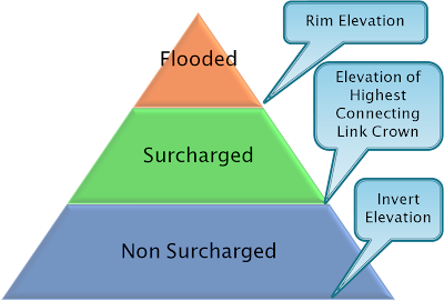


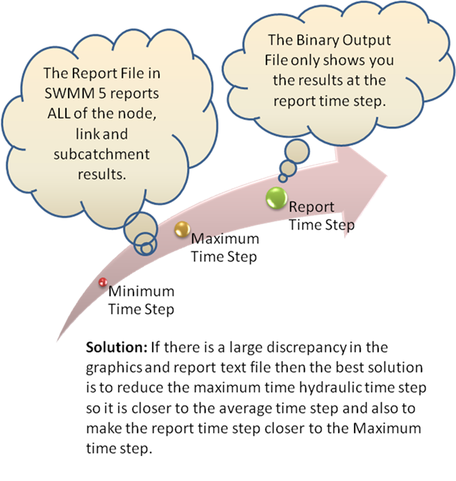

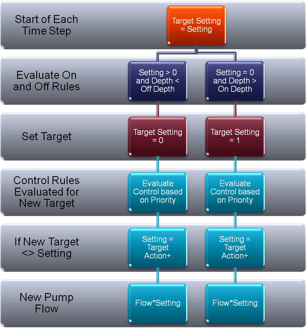